![]() |
Photo #1
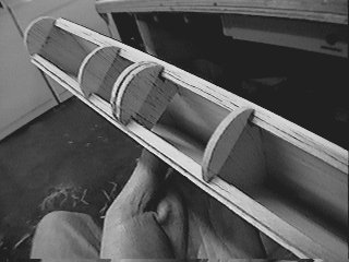
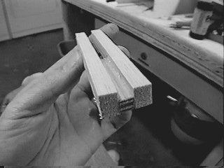
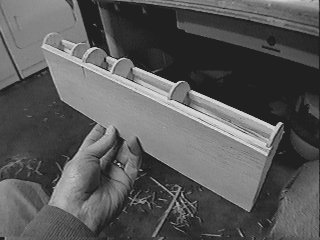
The flap is constructed in much the same way as the aileron, except the leading edge radius is larger, so you can bend a piece of 3/32" sheeting to form the leading edge. Al Master's suggestion of wrapping the wetted sheeting around a broomstick worked well, although I ended up cutting this piece a bit short before forming it. |
![]() |
Photo #2
Here is a close-up of the flap leading edge. Note the two extra formers spaced closely together. These are the supports for the formica control horn that I will glue in later after finish sanding, but before painting. |
![]() |
Photo #3
This is the flap hinge dowel support piece. It is made from 5/32" balsa and a small piece of 1/4" plywood in the middle. The dowel will be secured to the plywood with screws. |
![]() |
Photo #4
Here the two inboard flap hinge dowel supports are glued in place. Holes will be cut in the top sheeting to make this area accessible. The dowels have to be pulled out all the way to get the flap loose and remove it. You could mount the flaps permanently of course, but it is nice to have things serviceable. It also makes finishing & painting a bit easier. |
![]() |
Photo #5
Here is the outboard (right-hand) flap hinge dowel support piece glued
in place between ribs 5 & 6. Access to this dowel is through
the aileron spar. The ailerons have to be removed first, of course.
|
![]() |
Photo #6
Here is the slot in the aileron spar to access the dowel. The wingtip is to the right in this picture. The flap will go to the left. |
![]() |
Photo #7
Here is a view of the wing center section, right before the bottom sheeting is applied. In the lower part of the picture you can see the flap hinge supports. In the middle section you can see the 1/4" ply wing bolt plate, secured with 3/4" triangle stock glued against the #1 ribs. Here you can also see the short sections of 1/2" triangle stock glued against the top sheeting. This is for sheeting support where the wing saddle of the fuselage rests. In the forward section you can see W1 braced with triangle stock, the air tank for the main landing gear, and the square plastic tube conduits for the flap and aileron servo wires. |
![]() |
Photo #8
Here is the flap servo, mounted to a 1/8" lite ply plate with two pine blocks to hold the screws. This assembly gets flipped over and installed face down into the bottom of the wing. |
![]() |
Photo #9
Now you can see the flap servo plate mounted on 1/4" hardwood rails in between ribs 2 & 3. The pushrod goes through a hole in the spar and will exit the skin near the flap leading edge. |
![]() |
Photo #10
Close-up of the square plastic tubing used as a conduit for the servo wires. |
![]() |
Photo #11
Close-up of the flap pushrod. I'm using all 4-40 hardware. |