![]() |
Photo #1
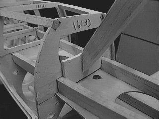
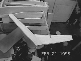
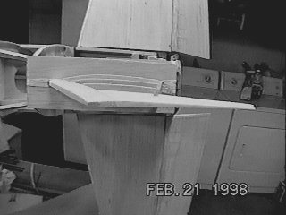
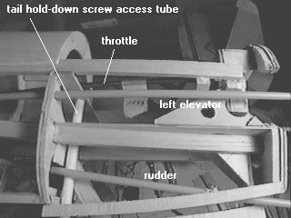
The basic framework of the lower fin. The leading edge is 3/8 x 1/2, the spar is 1/8" ply. I had to move the spar forward because of the scale hinge style I chose. 
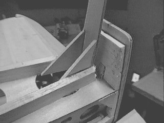
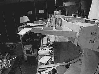
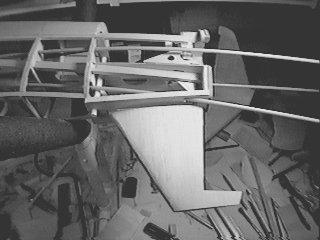
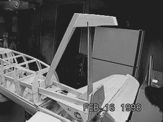
I debated whether to make the lower fin removable. I was afraid of what would happen in the event of a gear-up landing. I decided in the end that the structure would probably survive it, especially if I reinforced it just a bit, without adding too much weight. I was also afraid of a removable unit separating in flight. |
![]() |
Photo #2
The plans showed the leading edge extending only just below the lower skin. I decided that for just an ounce or two I could extend it down to F19, which would make it much stronger. Note the added piece of 1/8" lite ply behind F19. This was needed because of the hole in F19. Note also just below this the hole in the tank support for access to the tail hold-down screw. |
![]() |
Photo #3
The plans showed the lower fin spar butting up against F20. Since it had to be moved forward, it no longer rests against F20. I therefore reinforced it with 1/8" lite ply gussets. These gussets are glued to the crutch pieces. |
![]() |
Photo #4
Here is a plan view of the framework. You can see the gap between the spar & F20. |
![]() |
Photo #5
The fin ribs are added. These are just rectangular pieces of 3/32" balsa. I "upgraded" the sheeting here from 1/16" to 3/32" to make a slightly stronger structure. The plans called for 1/16" ribs and sheeting. Note also here the fuse bottom pieces that go around the root of the fin. These are 5/16" hard balsa for strength. These pieces will be hollowed out later for lightness. Weight in the tail is critical! Every extra ounce here will mean 2 oz. of lead in the nose. |
![]() |
Photo #6
The fin framework after sanding. Note the airfoil shape and the thinness of the tip! The bottom is left as a separate piece intentionally. On the real Do 335, this piece was a spring-loaded, shock-absorbing skid! Because it fit up inside the fin, there is a break in the outline. |
![]() |
Photo #7
Edge-on view of the fin framework. |
![]() |
Photo #8
Rear view of fin framwork. Note taper. |
![]() |
Photo #9
The lower fin is sheeted with soft 3/32" balsa. In preparation for applying the rear fuse sheeting, all pushrods are
routed to their final locations. Clearances are checked. Note
the white plastic tubing at left next to F19. This is the access
hole for the forward tail hold-down screw. An 8-32 nylon bolt will
be used (they're very light and strong).
|
![]() |
Photo #10
Close-up of the rear fuse before sheeting. At the bottom of the picture is the rudder pushrod. In the upper part of the picture, the white pushrod that goes through the middle of the engine cutout is for the left elevator. Harder to see is the red throttle pushrod, it has the masking tape tag labeled "rear" on it. |