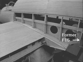
Here is the wing-fuse joint from above, before the lower rear fuse work is begun.
|
Photo #1
Here is the wing-fuse joint from above, before the lower rear fuse work is begun. |
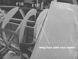 |
Photo #2
This area of the fuse was one of the most difficult to visualize and "think build." Once the side sheeting was applied, though, and the wing attached, it started to make more sense. It's one of those things that you need to see and manipulate in three dimensions before it starts to materialize. The wing-fuse joint in the rear is formed by two 1/4" soft balsa formers. You can see the rear one labeled in the picture at the trailing edge of the wing. Note that wax paper has been placed around the wing TE to keep from
gluing the former to it. After this picture was taken, I glued the
forward former to the wing TE, leaving the wax paper in place between the
two formers where the joint will be.
|
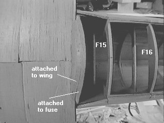 |
Photo #3
Using a T-bar, I sanded the two wing-fuse joint formers to the contour formed by the two fuse formers behind them, F15 & F16. The wing was then removed and sheeting was applied. See the result below. |
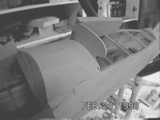 |
Photo #4
We start by cutting the air scoop cross-section using the template from the plans. This is from 1/8" lite ply. This piece will hold the dowels which will hold the whole assembly to the fuse. A 6-32 nylon bolt will hold the rear. Making this lower air scoop removable costs almost nothing in terms of weight, but adds alot in servicability. I'm actually looking forward to servicing this airplane! Every area of the fuse containing components that will need service is easily accessible. I've cursed over too many airplanes that had no removable hatches - and components requiring service buried deep within structures with limited access. It's just not worth it!!! |
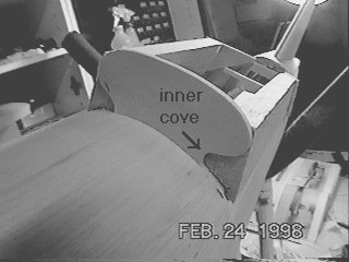 |
Photo #5
Close-up of the lite ply template and side blocks. Soft 1/2" balsa is used for the blocks. Inside the block on the right you can just see a smaller inner block that was needed to fill in the hole in the inner cove next to the skin. |
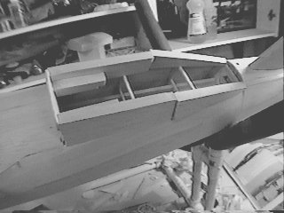 |
Photo #6
All side blocks have been added. You can clearly see the inner cove filler blocks in this view. |
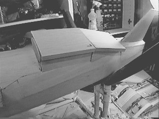 |
Photo #7
The bottom blocks are added. Thick CA is used throughout. The blocks are tack-glued to the fuse with a couple of small drops of thick CA. |
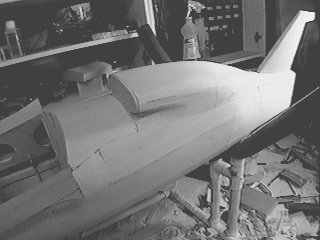 |
Photo #8
The main part of the scoop is carved and sanded to rough shape. |
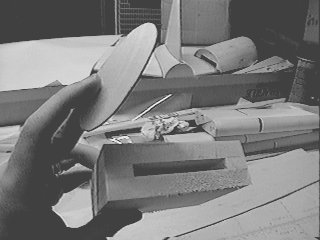 |
Photo #9
The forward part of the air scoop is made from an open-ended "box" of
1/2" balsa. The front face is made from 1/16" ply.
|
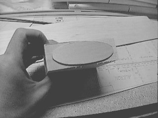 |
Photo #10
The front face of the scoop is glued onto the blocks with thick CA. |
 |
Photo #11
The (nearly) finished lower air scoop. Some filler will be needed
in the area between the forward part of the scoop and the fuselage.
|
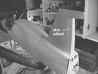 |
Photo #12
The lower rudder work is begun. I had to add some skin to make the rudder hinge line in the right place. It seems the lower fin spar ended up too far forward and at the wrong angle. It doesn't really hurt anything, it just means there's a larger void between the spar and the lower rudder. I used 1/8" soft balsa for the addition to give it a little extra strength. |
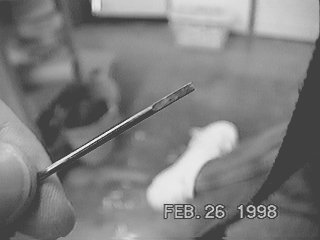 |
Photo #13
This is the lower end of the 3/32" music wire torque rod that connects the upper and lower rudder halves. It (happily) goes through the engine area just between the mount and the rear of the engine. I filed flats on both sides of the lower end, which will fit into a flattened piece of brass tubing glued into the rudder. |
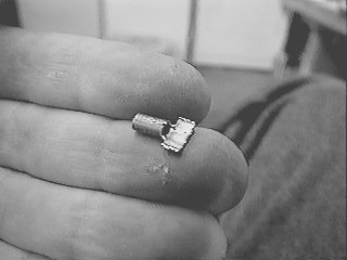 |
Photo #14
Here is the flattened brass tubing. The lower part is cut and spread open to provide additional leverage once this is glued into a balsa block in the lower rudder. |
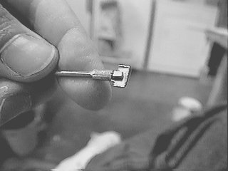 |
Photo #15
Here is the wire fitted inside the flattened tubing. This is the lightest linkage I could think of that would be sufficiently robust. The lower end of the music wire had to fit through the 3/32 hole, so I couldn't solder anthing to it directly. |
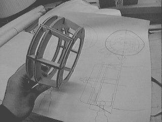 |
Photo #16
Sneak peek! Here is the foward cowling framework. This is the first thing I've designed and built using a CAD program. I used AutoCAD on my Sun workstation. The result? Faster design and *perfect* parts fit. My local blueprint shop will plot my creations for 80 cents per square foot. If you do this, be careful to ask what the prices are for different kinds of files. At our shop (Penninsula Blueprint) the charge is very different (3.50 per sq. ft. !!!) if you supply a .dxf file versus a "plot" file (.80 / sq ft). I've ordered ModelCAD for my PC. I don't expect it to measure up to AutoCAD, but I want the convenience of being able to print templates for parts 8-1/2 x 11 or smaller. I have a fiberglass forward cowl from Al Masters, but
|
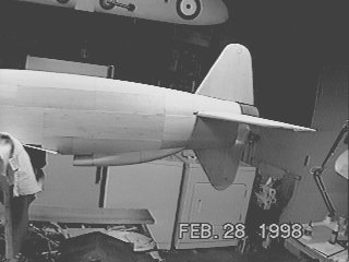 |
Photo #17
Here is the finished rear fuse. Looking good!
|