October 24, 1997 - part 2

The Canopy is framed up

 
The canopy frame is made up with 3/32" plywood.  I left about 1/16" thickness to allow for the plastic that will be glued over the frame. 

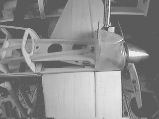
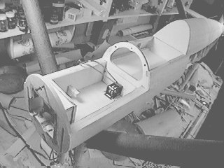
Note the paper instrument panel.  This was created by scanning a photo of the real instrument panel and drawing over the image with a CAD program.  The resulting drawing was then scaled to the proper size and printed.  I'll use this as a pattern when I make the instrument panel from sheet plastic.

 
The canopy in the open position.  I've got some dollhouse hinges (brass) that I will use for hinging.  I'm not sure how I will secure it yet, probably with some 2-56 socket head screws through the canopy sill, accessed through small holes in the canopy.
 
Here are a few shots of the tail section - I just got the spinner back from Tru-Turn.  They made the only 3-1/4" spinner that I could find in the proper shape.  I had to get them to do a special cutout for the pusher prop - this cost only about $15 extra.
 
The tail section from below left.  The spinner is a bit short of scale length, but it is close enough for "sport-scale."  Note close proximity of elevator and engine head.
 
Close-up of carburetor area.  Note the throttle arm right next to the stab skin near the hinge line.  The throttle linkage runs right through this part of the 1/4" x 1/2" stab "sill", which is braced against the triangular rear firewall brace.  This brace can be seen in this photo, it is the piece with two round holes cut into it.  Much of this had to be cut away to clear the carburetor and rear engine.
 
Tail section.  Rudder and elevators at maximum deflection.  The rudder is driven by a steering shaft that runs down next to the firewall, between the engine mount and the carburetor, and down to the lower rudder.  This shaft is bent at 90 degrees on top, and fits into a slot in the lower rudder.  This allows the entire stab-fin assembly to be removable.
 
The upper forward fuselage with hatches and canopy removed.  The canopy area is lined with .010 sheet plastic, so it can be painted without having to fill the woodgrain.
 
Lower fuselage hatch in the open position.  It is held on by one screw in the front and 2 screws in the back.  The reason for two screws in the rear is that a centered screw would not be accessible because of the nosegear strut. 

Note the frame for holding the retract valve.  The retract servo will be mounted just forward of the valve, you may be able to just see the outline of the servo drawn on the wood.